[Vero] D*A*M Fuzz FZ-673 Custom Project

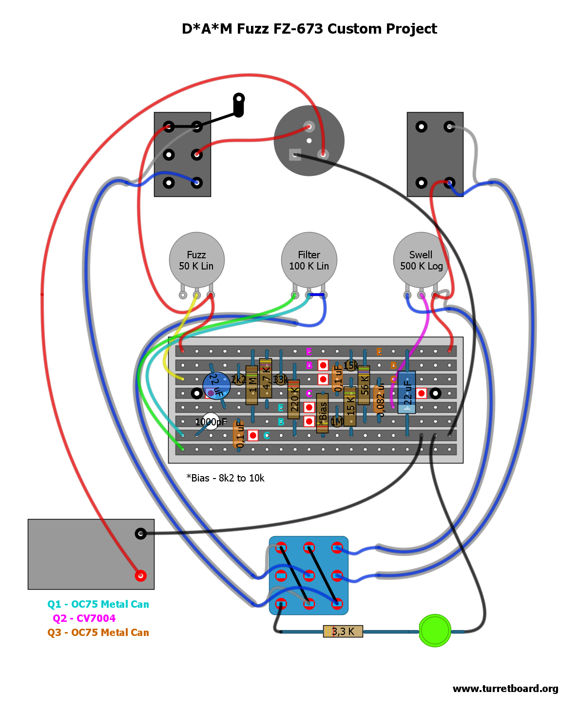
One of the newest D*A*M custom project creation. As far as I know only 10 was made, and no more will ever be. This project is based on Zonk Machine / MK1 Bender with little ad-ons that I really like here. Firstly, mostly notable is that filter/tone control was added – it’s my favorite tone mod I did in lot of my builds firstly seen in Joe Gagan’s Easy Face. To the standard 1000pF cap another bigger one (.1uF) is mixed in. Simple, but lovely solution! Tone pot value is just guess but I’m pretty sure it’s fine. Other than that standard PNP germaniums, modern addition of statut LED, and some components are shifted here and there. Cool unit!

Update 28.09.2011 New layout with shielded wire off-board wiring was added

Download D*A*M Fuzz FZ-673.pdf

————————————————————————
IMPORTANT UPDATE 13/06/2012

Due to D*A*M counterfeit pedals that recently appeared on the marked all D*A*M straight layouts will be removed from turretboard.org and will be replaced soon with our own works and interpretations.
————————————————————————

[0.15″ pitch Veroboard] Hornby Skewes (JHS) Zonk Machine

UPDATE 21 March 2012: Files are updated – now with full off-board wiring

Two layouts presented for original JHS parts layout. The one marked as Version I is based on D*A*M user named Graham, serious collector of number of fine vintage units, the other one – Version II is based on the schemo posted by David Main on D*A*M forum years ago. As you see part values are different. I’m sure both are accurate, but… In David’s schematic Q3 collector cap is listed as 0,47uF. In all gutshots I’ve seen there was always 0,047uF, Tropical Fish type, or orange cap 250v rated with R.S. (radio shack?) marking. So I think 0,47uF is wrong in Dave’s schemo. I left it matched to the Dave’s schemo (nah! 😉 updated to correct value in rev.2), but please have it in mind building your clone. Other BOM guide includes: 25uF electrolytic cap is 25v rated, bigger can be bitchy to fit. BC or Phillips should fit nicely. Vero is screwed directly to the enclosure, no standoffs, just a insulation to prevent circuit short.

Version III Prototype. I don’t know much about orgin of this variant. Looks very like a early Zonk Machine attempt. It has similar component values to my first two Zonk draws, but we see some differences like 64uF power filtering capacitor, flying input and output components. Some parts like input capacitor, or potentiometers value are just my guess, as I can’t see numbers on those picts I have – I’ve took the values from those two layouts I did erlier. I’ve seen total of 3 unit pictures like the one I’ve drawed here, one of them was sold on ebay months ago was different than other two. It had at least one Si transistor, and (I think) bias trimmer, the other two was without adjustable bias and with Ge trannies all the way up and this is what my layout is based on. If you have similar unit to this one, and can confirm values, or add anything to straight up the story of it, please @me.

Version I layout.pdf

Version II layout .pdf

Version III layout [prototype].pdf

[Tagboard] Sam Ash/AstroTone Fuzz

Happy birthday Doug 😉

Presented caps are ceramic disc, like in original unit, I have some big ass RMC brand 47n’s ready for this project 🙂

I’m still not sure about the diodes… In most iternal shots I’ve seen there was a huge badass diodes with orange caps, looks very much like my stock of 270’s… Those are germanium not Si like most forumities claims, but in other hand – diode look varies depend of manufacture. I guess experimenting is way to go. Otherwise if you know something I don’t know, email me

[Vero] Marshall Supa Fuzz

This layout matches original 1968 Marshall Supa unit, component placement and trace cuts are dead accurate to the unit I traced from, sadly, only from the pictures 🙁 Check out YT clip below for some additional porn, LMAO after I’ve watched it

Supa Porn Demo

Update 27.09.2011:

Few more Supafuzz variant. All layout are based on gutshots of original units, they’re different from each other and are all worth to try:

– Marshall Supa Fuzz.pdf

Marshall Supa Fuzz MK2.pdf

Marshall Supa Fuzz MK2 + 100R.pdf

Marshall Supa Fuzz Proto.pdf

Marshall Supa Fuzz PCB.pgn

Presented layouts includes full off-board wiring with shielded wire, no LED, no power supply socked – as original! Old files deleted

[Tagboard] Marshall Supa Fuzz Mk1 Proto

Heres Mk1, not as much clean as the mk2, but it has more parts, and I’m tired. I may give it second shots later on. To me this one is odd, no fixed bias resistor for Q1 collector like in later benders, so it receives full -9v, perhaps on the original there is a fixed bias resistor hidden under the vero? Maybe not, Tone Bender Mk1 is build without Q1 fixed resistor as well. I have just the only one schemo floating on the web done by I don’t know who, and the vero done by Electric Warrior, and to be honest I just starting to give it a born, so… Maybe someone more knowable than me can resolve this. If you really need to have fixed bias resistor then you can run the resistor (10k or so) from the power source to free tag space, and relocate the Q1 collector point there (showed on my layout)