[PCB] Fulltone Soul-Bender

Here’s Fulltone Soul-Bender PCB project. Full off-board wiring included. Direct copy of my unit S/N 3159, so it’s one of the last ones. It took me long time to make this project happen as I was not sure of my tracing abilities. The schematic I’ve drawn was so much different from Madbean’s Pastyface ,or classic MK3 Bender family. Anyway, now I’m sure it matches mine unit 100% minus in/out pull-down resistors. Some earlier units have some component differences like 150pF cap in place of 330pF, 47k resistor in place of 22k in mine. Also Volume knob value is different. In mine it’s 250kB, in first units it’s 500kA. More differences includes – old units have 100nF input, and collector Q3 caps, in place of 220nF in mine , and 100pF in place of 220pF ceramic in mine between collector and base of Q2.  Strange value of LED limiting resistor, very large, I think to limit power consumption, LED’s often eats several times more current than whole circuit.

Download Sour-Bender PCB project files.pdf – standard, typical CBE transistor arrangement, and CEB transistor arrangement project file for those who have those odd Russian wonders

Here’s drawn of close to original layout image for education purpose

Vero layout coming soon

[vero] VOX Repeat Percussion

VOX Repeat Percussion tagboard layout with full off-board wiring. This is modded version with Depth control addition. Lot of wire connections, but that’s what you have to deal with to have it looking nice. Set it under the board as well as all horizontally orientated components – this is personal thing, I do that with my builds for cleaner look

VOX Repeat Percussion Tagboard project file [.pdf]

Old stripboard layouts soon to be replaced with new versions with all flat-down components and full off-board wiring – stay tuned

VOX Repeat Percussion – stock.pdf

VOX Repeat Percussion – ring mod.pdf

VOX Repeat Percussion – ring mod LED.pdf

No off-board wiring this time

Tone Bender Family

Tone Bender MK2 Professional revision2

VOX Tone Bender – or JEN Fuzz, those are the same. I made vero layout that matches PCB pattern, for those who (like me) don’t like to play with chemicals at home. Component values matches my JEN unit. I’ve seen some differences in other VOX/JEN units, like 15uF electros, or different input cap values, but the ones listed in .pdf are most common from those I’ve seen. I’ve made my document with Tropical Fish Caps in mind, if you’re going to use other (axial) caps this can be easily modificated, just move the line, and the trace cuts as I did in my clone below. If you need assistance, @ me.

Tone Bender MK1 Vero – description in progress

Tone Bender MK1 on perfboard – exact repro, full off-board shielded wiring. This is the very first one from the whole family, originally build point to point on perfboard.

Tone Bender MK I.V.pdf – Very alike to good old Fuzz Face, but sounds not the same. Replica layout, full off-board wiring with shielded wire, as original – no LED, no power supply socket.

Another MKII variant. Or like I like to call it MK 1-3/4, or  STFU (Short-Circuit-Board Transitional Fuzz Unit). As I said above it’s basically earliest know to mankind MKII, build around of MK I.V vero design. Few components ware added, but still lacks pull-down capacitor on the input. It have unique sound compare to later MK Two’s. Below, two versions available to download, minor differences, but they are exist:

Sola Sound/D*A*M SCB Reissue.pdf – current D*A*M/Macari’s reissue, also known as Blue Meanie

Sola Sound/D*A*M SCB Reissue + 100R Limiting Resistor.pdf – I’ve seen just one unit like this – actually one picture of one unit, but it was easy to draw. Other MK2’s (Marshall Supa-Fuzzes) with limiting resistors I’ve seen always had 100R there (color code is not visible here). AFAIK not many was made, just a couple for Mr.Main own amusements, but worth mentioning

Original Short Circuity 60’s version.pdf – stock, vintage spec


Standard Tonebender Professional MKII, this is the layout of MKII we see most of the times. No surprises here, replica layout, again full shielded wire off-board wiring, no LED, no power supply socket – MKII Professional.pdf

The same as above, the only difference is 15000pF input and output caps resulting deeper tone. This spec is often seen in Sola/D*A*M reissue creations, as well as in some VOX MK2 Pros and Marshall Supa Fuzz. Download .pdf project file here

All presented layout includes full off-board wiring with shielded wire, no LED, no power supply socket – as original!

Here’s MK3 and MK4’s vero layouts. Those was build on PCB’s originally so this is not direct replica. I had mine C-E-B short leg transistors in mine drawing this (you can use any long leg transistors really with no problem), as well as those sexy orange Philips MKT’s. Tropical Fish caps will also fit here nicely.

Tone Bender MKIII – Early Spec

Tone Bender MKIV Later 1970-72 Spec

Tone Bender MKIV 1972-76 Batman Logo

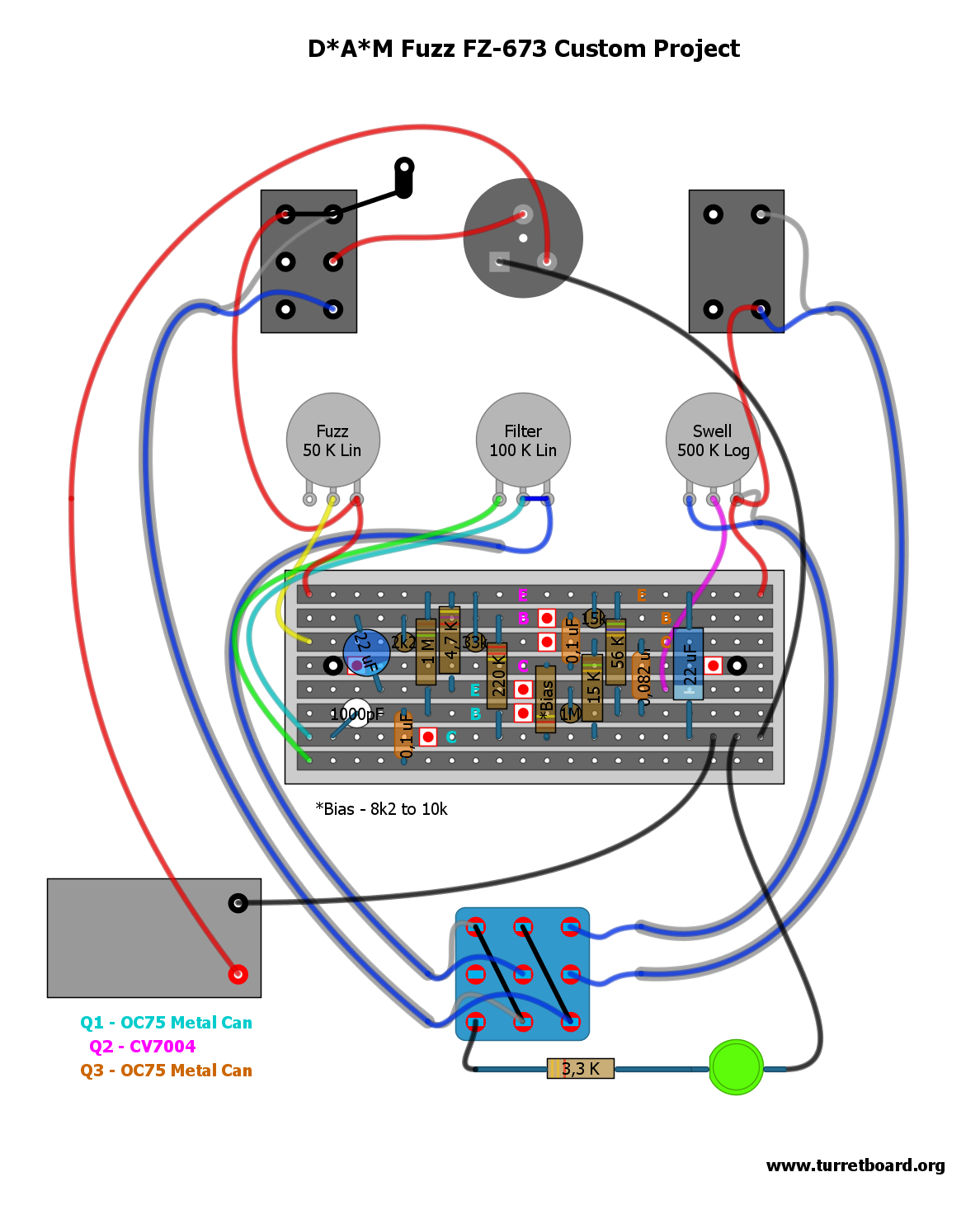
Here’s few more MK3(isch) projects. What’s common to those above is transistor pinout, and overall layout in most of the cases. Those all basically belongs to TBMK3/4 family, so I decided to post them here:

DAM Fuzz Sound MK3

DAM Fuzz Sound Black On Black Limited Edition

DAM Mother Fucker limited custom project – Grease and Smoke sides done as an independent units

Prescription Electronics – Yard Box

Another MKII. This is what I did after moving parts around in DAM Professional MkII I did recently.

Basically this is the same thing than DAM’s discontinued MKII, with on-board Q2 bias trimmer – only smaller. Small enough to fit into B sized hammond brand (or similar) enclosure. Use 0.1″ pitch stripboard, radial ecaps, small raster (5mm) 10nF and 100nF caps like Panasonic SMF, or Xicon Greenies and 1/4W resistors of your flavor, then enjoy Pocket Bender.pdf

Now – Back On Tag! Two new tagboard layouts for Tone Benders.

Tone Bender MKII

Standard schematic, you can build shitload of Bender variants including Marshall Supafuzz Input cap-to-ground can be easily take off the circuity without moving parts around, or use small-ass SPDT to switch it on or kick it out. Layout includes fully shielded off-board wiring and mojo vibe.

Another one is Tone Bender Mk I.V similar apparition, based on standard well know schematic, full offboard shielded wiring

And here is tag board layout for Vox Tone Bender.

UPDATE 25/06/2012:

Here’s universal layout for MKIII/MKIV type tone benders on 20×8 .15″ stripboard with listed part values for most common versions:

Get the pdf project file.

Get the png project file.

[Vero] D*A*M Fuzz FZ-673 Custom Project

One of the newest D*A*M custom project creation. As far as I know only 10 was made, and no more will ever be. This project is based on Zonk Machine / MK1 Bender with little ad-ons that I really like here. Firstly, mostly notable is that filter/tone control was added – it’s my favorite tone mod I did in lot of my builds firstly seen in Joe Gagan’s Easy Face. To the standard 1000pF cap another bigger one (.1uF) is mixed in. Simple, but lovely solution! Tone pot value is just guess but I’m pretty sure it’s fine. Other than that standard PNP germaniums, modern addition of statut LED, and some components are shifted here and there. Cool unit!

Update 28.09.2011 New layout with shielded wire off-board wiring was added

Download D*A*M Fuzz FZ-673.pdf

————————————————————————
IMPORTANT UPDATE 13/06/2012

Due to D*A*M counterfeit pedals that recently appeared on the marked all D*A*M straight layouts will be removed from turretboard.org and will be replaced soon with our own works and interpretations.
————————————————————————

[0.15″ pitch Veroboard] Hornby Skewes (JHS) Zonk Machine

UPDATE 21 March 2012: Files are updated – now with full off-board wiring

Two layouts presented for original JHS parts layout. The one marked as Version I is based on D*A*M user named Graham, serious collector of number of fine vintage units, the other one – Version II is based on the schemo posted by David Main on D*A*M forum years ago. As you see part values are different. I’m sure both are accurate, but… In David’s schematic Q3 collector cap is listed as 0,47uF. In all gutshots I’ve seen there was always 0,047uF, Tropical Fish type, or orange cap 250v rated with R.S. (radio shack?) marking. So I think 0,47uF is wrong in Dave’s schemo. I left it matched to the Dave’s schemo (nah! 😉 updated to correct value in rev.2), but please have it in mind building your clone. Other BOM guide includes: 25uF electrolytic cap is 25v rated, bigger can be bitchy to fit. BC or Phillips should fit nicely. Vero is screwed directly to the enclosure, no standoffs, just a insulation to prevent circuit short.

Version III Prototype. I don’t know much about orgin of this variant. Looks very like a early Zonk Machine attempt. It has similar component values to my first two Zonk draws, but we see some differences like 64uF power filtering capacitor, flying input and output components. Some parts like input capacitor, or potentiometers value are just my guess, as I can’t see numbers on those picts I have – I’ve took the values from those two layouts I did erlier. I’ve seen total of 3 unit pictures like the one I’ve drawed here, one of them was sold on ebay months ago was different than other two. It had at least one Si transistor, and (I think) bias trimmer, the other two was without adjustable bias and with Ge trannies all the way up and this is what my layout is based on. If you have similar unit to this one, and can confirm values, or add anything to straight up the story of it, please @me.

Version I layout.pdf

Version II layout .pdf

Version III layout [prototype].pdf