UPDATE 21 March 2012: Files are updated – now with full off-board wiring
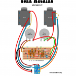
Two layouts presented for original JHS parts layout. The one marked as Version I is based on D*A*M user named Graham, serious collector of number of fine vintage units, the other one – Version II is based on the schemo posted by David Main on D*A*M forum years ago. As you see part values are different. I’m sure both are accurate, but… In David’s schematic Q3 collector cap is listed as 0,47uF. In all gutshots I’ve seen there was always 0,047uF, Tropical Fish type, or orange cap 250v rated with R.S. (radio shack?) marking. So I think 0,47uF is wrong in Dave’s schemo. I left it matched to the Dave’s schemo (nah! 😉 updated to correct value in rev.2), but please have it in mind building your clone. Other BOM guide includes: 25uF electrolytic cap is 25v rated, bigger can be bitchy to fit. BC or Phillips should fit nicely. Vero is screwed directly to the enclosure, no standoffs, just a insulation to prevent circuit short.
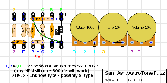
Version III Prototype. I don’t know much about orgin of this variant. Looks very like a early Zonk Machine attempt. It has similar component values to my first two Zonk draws, but we see some differences like 64uF power filtering capacitor, flying input and output components. Some parts like input capacitor, or potentiometers value are just my guess, as I can’t see numbers on those picts I have – I’ve took the values from those two layouts I did erlier. I’ve seen total of 3 unit pictures like the one I’ve drawed here, one of them was sold on ebay months ago was different than other two. It had at least one Si transistor, and (I think) bias trimmer, the other two was without adjustable bias and with Ge trannies all the way up and this is what my layout is based on. If you have similar unit to this one, and can confirm values, or add anything to straight up the story of it, please @me.
Version I layout.pdf
Version II layout .pdf
Version III layout [prototype].pdf
