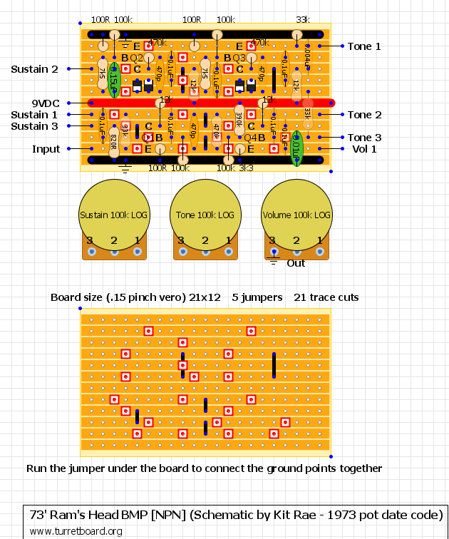
[vero] 73′ Big Muff Pi – Ram’s Head

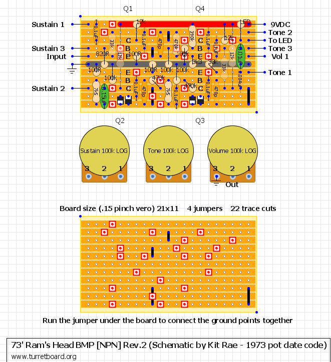
So… I have a lot of nice bigass ceramic caps and Ramshead build in mind, also 4pcs of 2N5133 new old stock with gain above 500hfe is here waiting. I did this layout with my parts selection in mind. I could track the grounding better but I decide to live it like that as the part layout is what I’m fancy with. I’ll run the jumper to connect the grounding points together.

I was drawing this from the layout found on Kit Rae’s website (awesome BMP info source). This layout is not verified for now.

Edited 10.04.2011: Old file deleted, new layout added. This is basically exact the same thing than before, but with better component routing. Input is closer to ground so using shielded wire is easier now. I like this layout way better now, I hope you feel the same 🙂 Also this one is smaller, even more than my Triangle Muff. Could be even more compact, but I still want to use my ceramic caps.

Edited 12.04.2011: I’ve spend some time today to make my Muff’s smarter. I’ve end up reducing two grounding points to only one, and make it even more compact (21×11 – I’ve never seen stripboard BMP that tinny)! Also LED limiting resistor is added to the layout. I think this is the final version 😉
Maestro Boomerang

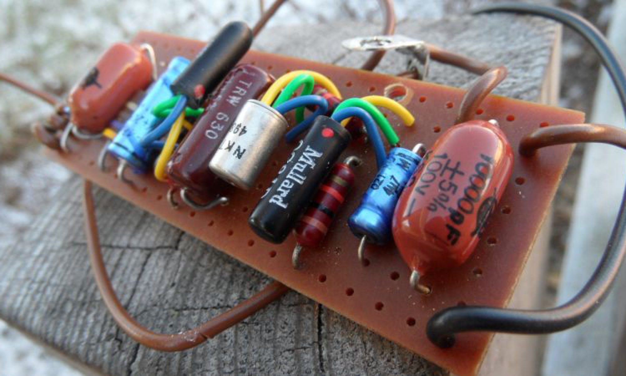
Here’s the Holly Grail Maestro Boomerang from Joe Gagan personal collection. Thanks Joe for your contribution!

Here’s what Joe says about his unit:

“after careful examination of this unit and another that sold on ebay in feb ’10 ( they had serial numbers only 2 digits apart!), i am convinced that the unit pictured here is 100% original, all solder joints untouched. original pot. unknown inductor mfgr.

gibson seems to have rushed this into production in the same year as the famous vox. disreali gears and hendrix created a huge demand for these suckers. it uses a patent first applied for in 63 by richard petersen, a resonant circuit designed to imitate a voice or trumpet ‘wow-wow sound” ( gibson owned lowry organs had this feature by around 64). even the schematic uses the term wow wow instead of wahwah.it seems that very few actual BG1s were made, however, and the BG2 boomerang came out in 68.

the BG2 used a different inductor, different pot manufacturer, and doubled as a volume pedal when the wah was off. one of the worst tonesucking pedals in history. but for the wah sound- in my direct comparisons the BG2s still do sound very close to the BG1 voicing and response curve.

[Vero] D*A*M Fuzz FZ-673 Custom Project

One of the newest D*A*M custom project creation. As far as I know only 10 was made, and no more will ever be. This project is based on Zonk Machine / MK1 Bender with little ad-ons that I really like here. Firstly, mostly notable is that filter/tone control was added – it’s my favorite tone mod I did in lot of my builds firstly seen in Joe Gagan’s Easy Face. To the standard 1000pF cap another bigger one (.1uF) is mixed in. Simple, but lovely solution! Tone pot value is just guess but I’m pretty sure it’s fine. Other than that standard PNP germaniums, modern addition of statut LED, and some components are shifted here and there. Cool unit!

Update 28.09.2011 New layout with shielded wire off-board wiring was added

Download D*A*M Fuzz FZ-673.pdf

————————————————————————
IMPORTANT UPDATE 13/06/2012

Due to D*A*M counterfeit pedals that recently appeared on the marked all D*A*M straight layouts will be removed from turretboard.org and will be replaced soon with our own works and interpretations.
————————————————————————

VOX Grey Wah-Wah

Another cherry on the cake from Jan. Rare example of Grey VOX, very first Wah-Wah ever produced. Here’s what Jan says about this pedal:

“The photos #5 and #6 shows the replacement pot with the pop-fixing-resistor(1M). The original pot (dual 100K linear is put away and will follow this pedal) did not perform properly. As it’s very hard (impossible??) to find really good dual wah-pots, I choose to put in a “Wah Potentiometer 50k lin / 500k lin” 4,50 EUR Product No: “ibawahpot” from Musikding (www.musikding.de). The 50K is for the Wah and 500K for the Swell/Volume. I took the opportunity to reverse the Wah to normal (Treble – toe down / Bass – heal down), it was very strange to have it in the opposite way. I have not revealed what’s under the cover, it remains a secret;-) So I do not know what components there are, what type of; inductor, capacitors and resistors, only the two transistors (BC150) is in the open.

Jan”

This is the second one gooped I ever seen. Also I have just a few picts of similar units and none of them had the duplo pot to control wah & volume/swell. There was always just a single potentiometer. AFAIK there was two basic layouts for this model. First one – also called prototype model was assembled by Del Casher (the inventor) himself and his wife. Those was build on tagboard. Later on the full production model with different component layout was issued, and pretty much looks similar to the one we see on picts here. Also AFAIR the early proto units was build with BC150 transistors, and in the production models usually we see Texas Instrument 2N3707, so this is another oddity. The inductor in later units was 250mH, resistors was Iskra brand, two big yellow unbranded 0,22uF 160v capacitors with similar look to WIMA’s, and two 10000pF (0,01uF) Styroflex type caps, as well as one bipolar 4uF. I’m not sure about the brand, but I think I see Lemco on it… Perhaps someone more knowable could add something to complete/verify the info.

Layout for Grey Wah is in “Layouts” -> “Wah & EQ” section on my webpage

Thanks to Jan again!

Marshall Supa Wah

Here’s Marshall Supa Wah porn. Pictures was sent by Jan from Sweden. This particular unit is faulty (missing inductor), but still beautiful! I hope Jan will get her to live very soon.

Some additional info from the owner…

Parts details:

1 x 10uF16V Electrolytic cap
2 x 0.01uF Lemco 10K ceramic capacitors
2 x .1uF/160V Mullard capacitors
2 x 2G374 901 Transistors
1 x 22K/.5W±5% Iskra resistor
2 x 470K/.5W±5% Iskra resistor
1 x 1K/.5W±5% Iskra resistor
1 x 10K/.5W±5% Iskra resistor
1 x 100K/.5W±5% Iskra resistor
1 x 470/.5W±5% Iskra resistor
1 x 68K/.5W±5% Iskra resistor
1 x 1K5/.5W±5% Piher resistor

So it’s matches the bill of material from my project files 🙂

Big cheers to Jan for the picts and BOM confirmation

[0.15″ pitch Veroboard] Hornby Skewes (JHS) Zonk Machine

UPDATE 21 March 2012: Files are updated – now with full off-board wiring

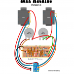
Two layouts presented for original JHS parts layout. The one marked as Version I is based on D*A*M user named Graham, serious collector of number of fine vintage units, the other one – Version II is based on the schemo posted by David Main on D*A*M forum years ago. As you see part values are different. I’m sure both are accurate, but… In David’s schematic Q3 collector cap is listed as 0,47uF. In all gutshots I’ve seen there was always 0,047uF, Tropical Fish type, or orange cap 250v rated with R.S. (radio shack?) marking. So I think 0,47uF is wrong in Dave’s schemo. I left it matched to the Dave’s schemo (nah! 😉 updated to correct value in rev.2), but please have it in mind building your clone. Other BOM guide includes: 25uF electrolytic cap is 25v rated, bigger can be bitchy to fit. BC or Phillips should fit nicely. Vero is screwed directly to the enclosure, no standoffs, just a insulation to prevent circuit short.

Version III Prototype. I don’t know much about orgin of this variant. Looks very like a early Zonk Machine attempt. It has similar component values to my first two Zonk draws, but we see some differences like 64uF power filtering capacitor, flying input and output components. Some parts like input capacitor, or potentiometers value are just my guess, as I can’t see numbers on those picts I have – I’ve took the values from those two layouts I did erlier. I’ve seen total of 3 unit pictures like the one I’ve drawed here, one of them was sold on ebay months ago was different than other two. It had at least one Si transistor, and (I think) bias trimmer, the other two was without adjustable bias and with Ge trannies all the way up and this is what my layout is based on. If you have similar unit to this one, and can confirm values, or add anything to straight up the story of it, please @me.

Version I layout.pdf

Version II layout .pdf

Version III layout [prototype].pdf

[Veroboard] Madbean Fatpants – EP-3 Pre with bonus

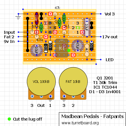
Yet another Ep-3 booster But with added control.

For details go to Brian’s site

http://madbeanpedals.com/

I was in need of small vero layout for this one to build into another pedal I’m modifying, so I’ve made it. Layout is sized for Panasonic Stacked Metal Films, as well as 25v Philips axial, Sanyo radial Os-Con’s and 1/2 resistors, as this is the thing I have and like to use.

I hope you like it

Thanks Brian for the ideas!

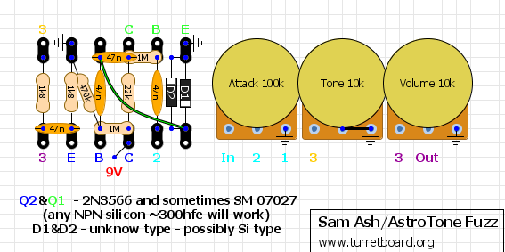
[Tagboard] Sam Ash/AstroTone Fuzz

Happy birthday Doug 😉

Presented caps are ceramic disc, like in original unit, I have some big ass RMC brand 47n’s ready for this project 🙂

I’m still not sure about the diodes… In most iternal shots I’ve seen there was a huge badass diodes with orange caps, looks very much like my stock of 270’s… Those are germanium not Si like most forumities claims, but in other hand – diode look varies depend of manufacture. I guess experimenting is way to go. Otherwise if you know something I don’t know, email me