
Another cool fuzz, it’s kind of stripped down Big Muff.
Small circuit with big tone.
Components layout is similar to the one in real unit, vero comes next
Boards and turrets! Yeah!
Another cool fuzz, it’s kind of stripped down Big Muff.
Small circuit with big tone.
Components layout is similar to the one in real unit, vero comes next
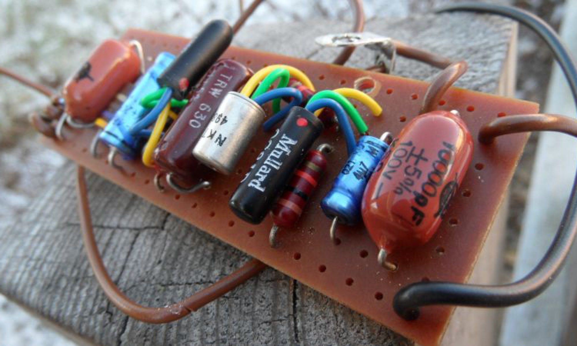
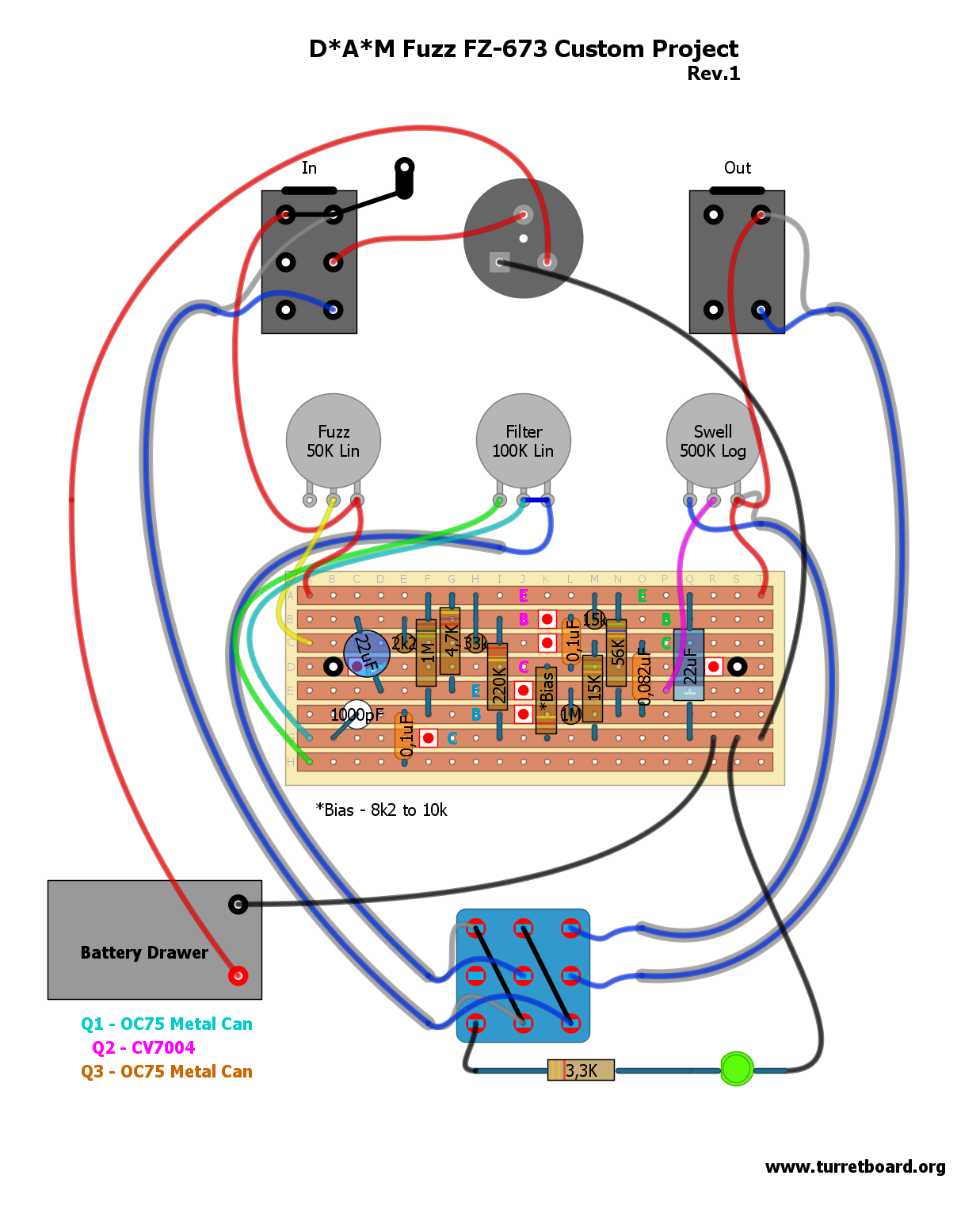
D*A*M’s latest one-off custom project MK1 Tone Bender variant. I don’t do much D*A*M stuff due to respect to Mr.Main, but one-offs is different story. Full off-board shielded wiring provided. Original have OC78 (Q1), OC45 (Q2) and OC78D (Q3 from left to right).
Project revised 8/03/2012
Small wiring error corrected
————————————————————————
IMPORTANT UPDATE 13/06/2012
Due to D*A*M counterfeit pedals that recently appeared on the marked all D*A*M straight layouts will be removed from turretboard.org and will be replaced soon with our own works and interpretations.
————————————————————————

Basically early 70’s BMP clone that has some unusual component values. Few sources on-line reports that this unit sound quite unique to classic Big Muffs. Sound of this unit is often described as somewhere between a Big Muff and an early ProCo Rat, angry fuzz/OD hybrid, but a lot smoother than older brothers. Originally build into foot controlled wah-wah enclosure where you can set the volume by foot.
Jordan Creator – Model 6000 with full off-board wiring
Current project is revised 06.06.2012. It fits now into standard Hammond B type enclosure, and contains more common parts raster
 Collection of few Big Muff variants. There’s no such thing as standard BMP schematic – To many variations was issued, and even the same model from the same year of production could sound different, since EHX didn’t care much about part selection.
Since I’m a BMP freak myself, you can expect many variants here on my website now and in future! All layouts are presented with full off-board wiring.
Current stripboard layouts are different than what it was here before. If you was working on one of previous versions email me, and I’ll send you old files. New layouts are way better routed and are cooler in general. Firstly – old layouts was done for odd parts I had on hand, some very unusual and hard to source. Current layout was designed to fix that, plus I had few more goals in mind:
– typical part raster, 5mm for most caps – ceramics, or film (easily takes Panasonic SMF’s), 2,5mm for clipping/blocking caps
– all resistors 1/4w and flat on board
– no jumpers (I’ve failed here, but still less than before)
– small enough to go with Hammond B
– it’s for .1″ pitch stripboard
One extra part unseen on schematic is 2M2 anti-pop resistor on input. Unusual 4nF ceramic cap in tonestack you can substitute with any closes value, like 3n9
All layouts bellow based on Kit Rae schematics
1973 Violet Ram’s Head – 1st Version
1973 Violet Ram’s Head – 2nd Version
And now – different layout for kind-off the same crap. The problem with layout above is lack of space to accommodate can type, radial e-caps. So I’ve started from scratch. Electrolytic caps needs more space, and here you have it. Also drawing this I was thinking about it as a universal layout for future triangle variants – most of those Triangles contains e-caps in different, not always the same spots. That’s why you see 2,5mm raster for non-polar capacitors – as it’s the same raster as most of electrolytic radial capacitors I have . My advice is to use WIMA MKS02 series caps for 100nF. Even 100nF-150nF/63V are 2,5mm. 10nF is 5mm in my layout – use MKS2 here, or anything 5mm, choice is wide, it’s common raster part.
Like I said, layout is different to the ones I’ve posted earlier, it’s bigger… but still fits small Hammond “B”, it’s not as nice as the ones posted before, has many trace-cuts, and jumpers (whom I hate), but this is the best I can do dude!
Just one layout for now, I’ll try to update (and finally finish it up ASAP)
J Mascis Red&Black – yeah I know, it’s not Triangle, but many will like it 🙂
And now, different flavor of the same good old crap
BMP with AMZ presence control. The base is the same overall layout as in J Mascis Red&Black, but only with component names (place your own favorite flavor) for everything other than tonestack.
For tonestack my choose was standard AMZ 1th version values. It’s open ended project, do your own Big Muff mix.
For more information about AMZ tonestack fallow this link
…more coming soon
———————
And now something I don’t do really. I’m more into vero and turretboard stuff. But I do PCB’s occasionally. My PCB pattern is designed for look and mojo, not the size. No matter what chicks says, size matters, bigger is better, at least for me (pedal-wise). Real man should have huge piece of equipment, that’s why we like big cars, half pounder Big Mac, and boooooooobs. For fuck sake, wipe your nose and be a man!!! Plus, this is BIG Muff, right? In short, it won’t fit in your B-sized enclosure (EDIT: well, now it will after endless revisions). DEM size E is what it needs really, as used by D*A*M or Cornish. After all I’ve made it for my own use… So, if you like to have nice discharge when changing battery, this may be for you.
Actually – this project was born months ago, and came through several changes and revisions. I wanted to make it perfect. It’s way smaller than first attempt, but still ballsy. Now you can put it also into Hammond 1590 J, or even better – into one of these cute pedalenclosures.com YY boxes, or common – boring as fuck Hammond “BB”.
Extra pads near capacitors are for larger components like axial BC electronic 1uF’s (I think 40v-63v I have, those lay down nicely), and the rest of the components I had in mind was bigass ceramics, tropical fish caps (or similar raster), and half watter resistors.
PAGE REVISION – All projects removed! Instead now you can download just one zipped file with universal project. Blank schematic with component numbers/names, matched component layout and PCB transfer files are there. Also DIYLC v3 project files are included, so all you have to do is open them up, place your own component values from schematic you have/like, print it up after you done and you’re ready to go.
Current PCB pattern is little different than previous version, I’ve changed C7 and R4 locations, so old file, and current project are NOT interchangeable
Great schematic source is Kit Rae Big Muff Page and to be honest the basic schemo I provide match component names of Kit’s schematics. If you will have any problems, concerns, questions – I’m always happy to assist, just trow me an email [go to Info & Contact page]
what else… ah, yeah!
Schematic and component layout shows electrolytic caps in most of the places, BMP schemos are different, sometimes there is no e-caps at all, so just use what the schematic is asking for.
Also different schematic asks for different electrolytic cap orientation. There is not much difference what orientation you’ll use. Electrolytic caps block only DC current, and your signal is AC. Since in BMP 1uF polarized capacitors are in signal patch you should have no problems either way, but it’s recommended to use orientation as per my schematic. Here’s the quote by Deltafred from FreeStompboxes explaining possible issues:
Polarised electrolytic capacitors work best if the the +ve side has a higher voltage on it than the -ve side.
They will tolerate a small reverse polarity (about 10% rated value IIRC – could be wrong). If you reverse bias them too much they start to act as resistors and conduct, very noisy resistors I seem to remember.
The trick is to asses (or measure) which side has the highest voltage on it and make that the +ve side. If one side goes to ground via a resistor or pot then that will (usually) be at 0v as far as DC is concerned so that side would be -ve.
For more info fallow this link
Here’s ZIPPED file I was referring to – BMP PCB Files [854 KB]

Baldwin-Burns Buzzaround.pdf – I’m not sure about ground tracking compared to real one, but other than that this layout matches original unit. Also, this is the same layout than used in D*A*M Fuzzaround
Page revision: 25 March 2012
Here’s vero layout for Buzzaround. It should easily fit small 1590B or 125B enclosure, additionaly trannies could be mounted on sockets, so You can swap them and pick best sounding trio. In original unit where used three NKT213 (very rare and pricy stuff nowdays…), but this is pretty elastic circuit and You can use other PNP Ge transistors.
D.A. Main of D*A*M reports that in orginal unit where used below gains:
Q1 – around 50hfe
Q2 – around 80hfe
Q3 – around 130hfe
Page revision: 05 April 2012
Added small tag board version – should easily fit 125B enclosure.

Here’s Fulltone Soul-Bender PCB project. Full off-board wiring included. Direct copy of my unit S/N 3159, so it’s one of the last ones. It took me long time to make this project happen as I was not sure of my tracing abilities. The schematic I’ve drawn was so much different from Madbean’s Pastyface ,or classic MK3 Bender family. Anyway, now I’m sure it matches mine unit 100% minus in/out pull-down resistors. Some earlier units have some component differences like 150pF cap in place of 330pF, 47k resistor in place of 22k in mine. Also Volume knob value is different. In mine it’s 250kB, in first units it’s 500kA. More differences includes – old units have 100nF input, and collector Q3 caps, in place of 220nF in mine , and 100pF in place of 220pF ceramic in mine between collector and base of Q2. Strange value of LED limiting resistor, very large, I think to limit power consumption, LED’s often eats several times more current than whole circuit.
Download Sour-Bender PCB project files.pdf – standard, typical CBE transistor arrangement, and CEB transistor arrangement project file for those who have those odd Russian wonders
Here’s drawn of close to original layout image for education purpose
Vero layout coming soon
One more project requested from Troy
This layout is presented with shielded wire off-board wiring, no LED, no power supply socket.
Download WEM Rush Pepbox.pdf project reversed 08 March 2012 – the early one was wrong
Update 19/06/2012 – Request from our favorite beta tester! Silicon Pepbox.pdf
Tone Bender MK2 Professional revision2
VOX Tone Bender – or JEN Fuzz, those are the same. I made vero layout that matches PCB pattern, for those who (like me) don’t like to play with chemicals at home. Component values matches my JEN unit. I’ve seen some differences in other VOX/JEN units, like 15uF electros, or different input cap values, but the ones listed in .pdf are most common from those I’ve seen. I’ve made my document with Tropical Fish Caps in mind, if you’re going to use other (axial) caps this can be easily modificated, just move the line, and the trace cuts as I did in my clone below. If you need assistance, @ me.
Tone Bender MK1 Vero – description in progress
Tone Bender MK1 on perfboard – exact repro, full off-board shielded wiring. This is the very first one from the whole family, originally build point to point on perfboard.
Tone Bender MK I.V.pdf – Very alike to good old Fuzz Face, but sounds not the same. Replica layout, full off-board wiring with shielded wire, as original – no LED, no power supply socket.

Another MKII variant. Or like I like to call it MK 1-3/4, or STFU (Short-Circuit-Board Transitional Fuzz Unit). As I said above it’s basically earliest know to mankind MKII, build around of MK I.V vero design. Few components ware added, but still lacks pull-down capacitor on the input. It have unique sound compare to later MK Two’s. Below, two versions available to download, minor differences, but they are exist:
– Sola Sound/D*A*M SCB Reissue.pdf – current D*A*M/Macari’s reissue, also known as Blue Meanie
– Sola Sound/D*A*M SCB Reissue + 100R Limiting Resistor.pdf – I’ve seen just one unit like this – actually one picture of one unit, but it was easy to draw. Other MK2’s (Marshall Supa-Fuzzes) with limiting resistors I’ve seen always had 100R there (color code is not visible here). AFAIK not many was made, just a couple for Mr.Main own amusements, but worth mentioning
– Original Short Circuity 60’s version.pdf – stock, vintage spec
Standard Tonebender Professional MKII, this is the layout of MKII we see most of the times. No surprises here, replica layout, again full shielded wire off-board wiring, no LED, no power supply socket – MKII Professional.pdf
The same as above, the only difference is 15000pF input and output caps resulting deeper tone. This spec is often seen in Sola/D*A*M reissue creations, as well as in some VOX MK2 Pros and Marshall Supa Fuzz. Download .pdf project file here
All presented layout includes full off-board wiring with shielded wire, no LED, no power supply socket – as original!
Here’s MK3 and MK4’s vero layouts. Those was build on PCB’s originally so this is not direct replica. I had mine C-E-B short leg transistors in mine drawing this (you can use any long leg transistors really with no problem), as well as those sexy orange Philips MKT’s. Tropical Fish caps will also fit here nicely.
Tone Bender MKIII – Early Spec
Tone Bender MKIV Later 1970-72 Spec
Tone Bender MKIV 1972-76 Batman Logo
Here’s few more MK3(isch) projects. What’s common to those above is transistor pinout, and overall layout in most of the cases. Those all basically belongs to TBMK3/4 family, so I decided to post them here:
DAM Fuzz Sound Black On Black Limited Edition
DAM Mother Fucker limited custom project – Grease and Smoke sides done as an independent units
Prescription Electronics – Yard Box
Another MKII. This is what I did after moving parts around in DAM Professional MkII I did recently.
Basically this is the same thing than DAM’s discontinued MKII, with on-board Q2 bias trimmer – only smaller. Small enough to fit into B sized hammond brand (or similar) enclosure. Use 0.1″ pitch stripboard, radial ecaps, small raster (5mm) 10nF and 100nF caps like Panasonic SMF, or Xicon Greenies and 1/4W resistors of your flavor, then enjoy Pocket Bender.pdf
Now – Back On Tag! Two new tagboard layouts for Tone Benders.
Standard schematic, you can build shitload of Bender variants including Marshall Supafuzz Input cap-to-ground can be easily take off the circuity without moving parts around, or use small-ass SPDT to switch it on or kick it out. Layout includes fully shielded off-board wiring and mojo vibe.
Another one is Tone Bender Mk I.V similar apparition, based on standard well know schematic, full offboard shielded wiring
And here is tag board layout for Vox Tone Bender.
UPDATE 25/06/2012:
Here’s universal layout for MKIII/MKIV type tone benders on 20×8 .15″ stripboard with listed part values for most common versions:


