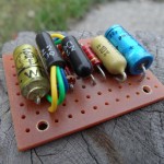
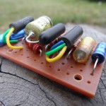
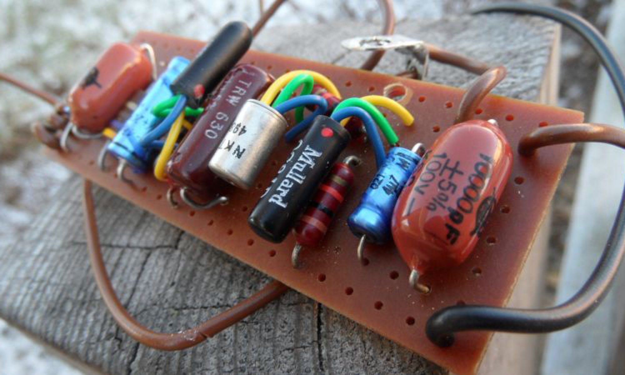
Tone Bender MK2 Professional revision2
VOX Tone Bender – or JEN Fuzz, those are the same. I made vero layout that matches PCB pattern, for those who (like me) don’t like to play with chemicals at home. Component values matches my JEN unit. I’ve seen some differences in other VOX/JEN units, like 15uF electros, or different input cap values, but the ones listed in .pdf are most common from those I’ve seen. I’ve made my document with Tropical Fish Caps in mind, if you’re going to use other (axial) caps this can be easily modificated, just move the line, and the trace cuts as I did in my clone below. If you need assistance, @ me.
Tone Bender MK1 Vero – description in progress
Tone Bender MK1 on perfboard – exact repro, full off-board shielded wiring. This is the very first one from the whole family, originally build point to point on perfboard.
Tone Bender MK I.V.pdf – Very alike to good old Fuzz Face, but sounds not the same. Replica layout, full off-board wiring with shielded wire, as original – no LED, no power supply socket.

Another MKII variant. Or like I like to call it MK 1-3/4, or STFU (Short-Circuit-Board Transitional Fuzz Unit). As I said above it’s basically earliest know to mankind MKII, build around of MK I.V vero design. Few components ware added, but still lacks pull-down capacitor on the input. It have unique sound compare to later MK Two’s. Below, two versions available to download, minor differences, but they are exist:
– Sola Sound/D*A*M SCB Reissue.pdf – current D*A*M/Macari’s reissue, also known as Blue Meanie
– Sola Sound/D*A*M SCB Reissue + 100R Limiting Resistor.pdf – I’ve seen just one unit like this – actually one picture of one unit, but it was easy to draw. Other MK2’s (Marshall Supa-Fuzzes) with limiting resistors I’ve seen always had 100R there (color code is not visible here). AFAIK not many was made, just a couple for Mr.Main own amusements, but worth mentioning
– Original Short Circuity 60’s version.pdf – stock, vintage spec
Standard Tonebender Professional MKII, this is the layout of MKII we see most of the times. No surprises here, replica layout, again full shielded wire off-board wiring, no LED, no power supply socket – MKII Professional.pdf
The same as above, the only difference is 15000pF input and output caps resulting deeper tone. This spec is often seen in Sola/D*A*M reissue creations, as well as in some VOX MK2 Pros and Marshall Supa Fuzz. Download .pdf project file here
All presented layout includes full off-board wiring with shielded wire, no LED, no power supply socket – as original!
Here’s MK3 and MK4’s vero layouts. Those was build on PCB’s originally so this is not direct replica. I had mine C-E-B short leg transistors in mine drawing this (you can use any long leg transistors really with no problem), as well as those sexy orange Philips MKT’s. Tropical Fish caps will also fit here nicely.
Tone Bender MKIII – Early Spec
Tone Bender MKIV Later 1970-72 Spec
Tone Bender MKIV 1972-76 Batman Logo
Here’s few more MK3(isch) projects. What’s common to those above is transistor pinout, and overall layout in most of the cases. Those all basically belongs to TBMK3/4 family, so I decided to post them here:
DAM Fuzz Sound MK3
DAM Fuzz Sound Black On Black Limited Edition
DAM Mother Fucker limited custom project – Grease and Smoke sides done as an independent units
Prescription Electronics – Yard Box
Another MKII. This is what I did after moving parts around in DAM Professional MkII I did recently.
Basically this is the same thing than DAM’s discontinued MKII, with on-board Q2 bias trimmer – only smaller. Small enough to fit into B sized hammond brand (or similar) enclosure. Use 0.1″ pitch stripboard, radial ecaps, small raster (5mm) 10nF and 100nF caps like Panasonic SMF, or Xicon Greenies and 1/4W resistors of your flavor, then enjoy Pocket Bender.pdf
Now – Back On Tag! Two new tagboard layouts for Tone Benders.
Tone Bender MKII
Standard schematic, you can build shitload of Bender variants including Marshall Supafuzz Input cap-to-ground can be easily take off the circuity without moving parts around, or use small-ass SPDT to switch it on or kick it out. Layout includes fully shielded off-board wiring and mojo vibe.
Another one is Tone Bender Mk I.V similar apparition, based on standard well know schematic, full offboard shielded wiring
And here is tag board layout for Vox Tone Bender.
UPDATE 25/06/2012:
Here’s universal layout for MKIII/MKIV type tone benders on 20×8 .15″ stripboard with listed part values for most common versions:
Get the pdf project file.
Get the png project file.


